17 Simulation of wireless mobile charger circuit diagram 17 Wireless power transfer allows a convenient, easy to use battery charging of mobile phones and other mobile devices. No hassle with cables and plugs, just place the device on a pad and that's it.

The ease with which the charger can quickly put a portable device in a charging state, is driving growth in the mobile and wearables markets. In addition to consumer devices such as smartphones and smartwatches, medical products such as blood glucose monitors and industrial bar code scanners are transitioning to wireless charging. Furthermore

PDF A Design Guideline of Wireless Charging Module Circuit Diagram
Wireless Charging System Architecture. We first level-set high-level system concepts before tackling detailed transmitter/receiver designs for context. Contactless Power Transfer Approaches
Protecting the wireless charging pad. The wireless charging pad power input is either a USB Type-C port or a proprietary DC input (Figure 6). Be sure to protect the DC input circuit from both overloads and transients. Protection is still necessary for the design, regardless of the power input in use.

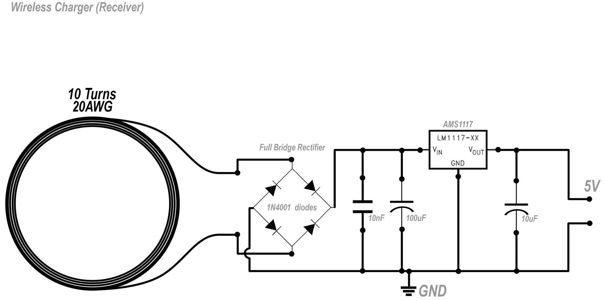
PDF Designing of Wireless Mobile Battery Charger Circuit Diagram
the receiving device (such as mobile phone), a minimum of 0.5mm of distance is required to reserve for the surface of the coil and the inner surface of the housing, so the thickness of interface surface of the housing should design within 1.25~2.0mm. The design layout of PCBA/transmitter coil/receiver coil will directly affected the debugging of allows charging devices to easily adapt to changing power levels. This is important to ensure compatibility with different types of consumer electronics devices, such as smart-phones and tablets. Qi Wireless Design Overview: The principle of wireless power transfer in basic terms is an open-air transformer consist-
