Heart rate sensor Circuit Diagram This sensor is designed using an attractive look with a heart logo. Also, it is a small one and very cheap. Therefore, you can buy it and check out your body's heart pulse rate easily. For that, I will guide you step by step through this tutorial. Also, this sensor is most important for athletes, students and software developers, etc. Keep
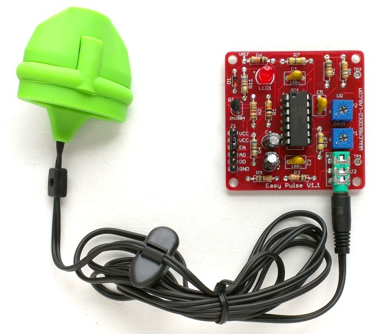
The Pulse Sensor is a low-power plug-and-play heart-rate sensor that is well designed. The sensors will signal to 16×2 display to show our pulse rate BPM. this sensor is easy to use and operate. Just place your finger on top of the sensor and it will measure the heartbeat changes. Required Material In this tutorial , you will need : Arduino

Monitor Heart Rate using Pulse Sensor and ESP32 Circuit Diagram
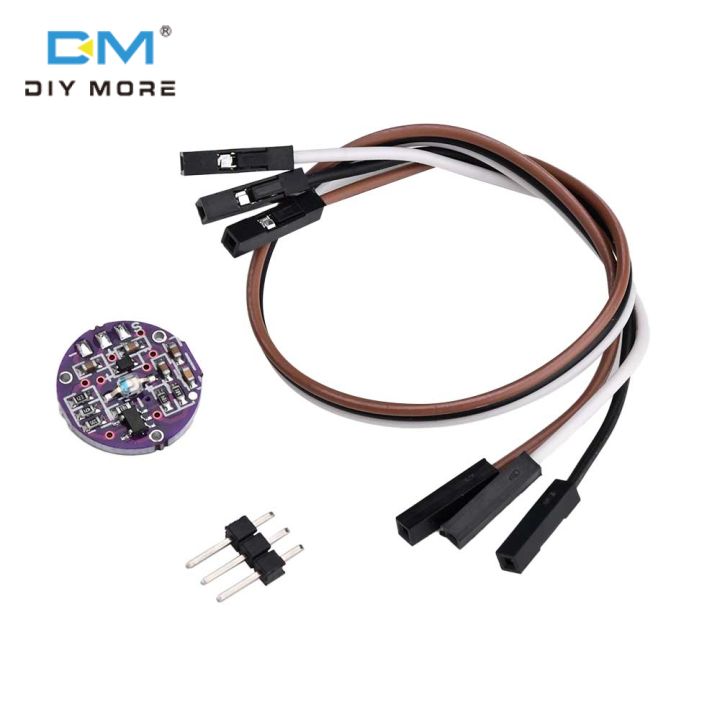
The MAX30100 sensor is used as both a heart rate monitor and a pulse oximeter. These features are enabled by the construction of this sensor which consists of two LEDs, a photodetector, optimized optics, and low noise signal processing components. It is easily used with microcontrollers such as Arduino, ESP32, NodeMCU, etc. to build an The Pulse Sensor developers have created software to visualize the Pulse Sensor data on your computer. It is written in the Processing programming language. This software displays all of the data that the Arduino receives from the Pulse Sensor. It plots the user's heart rate in real time.
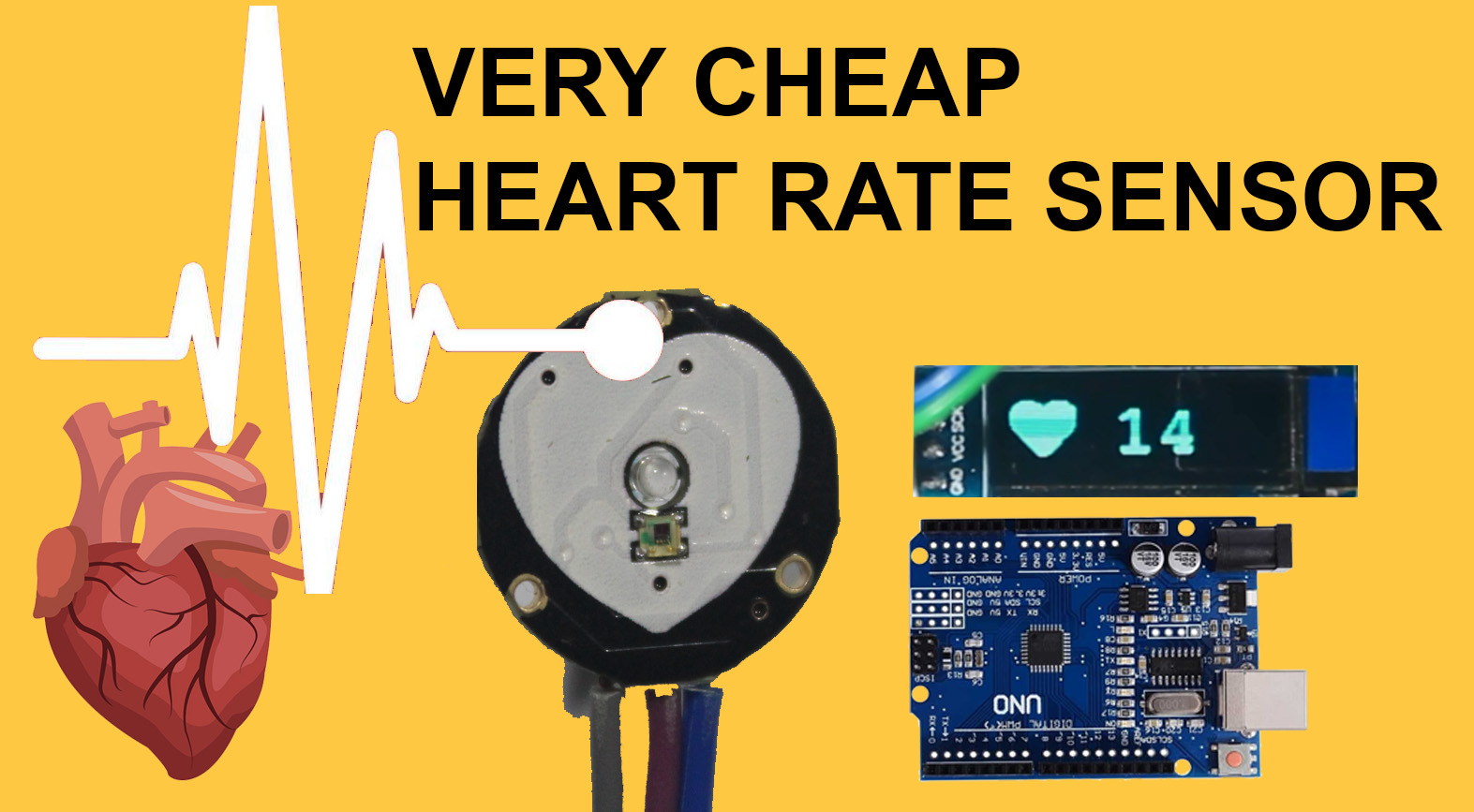
Monitor Heart Rate using Pulse Sensor and Arduino. SEN-11574 Pulse Sensor Introduction. The SEN-11574 pulse sensor is mainly used for sensing heartbeat rate. Normally it is a very difficult task to measure the exact heartbeat rate, but this has become so much easy with the help of this pulse sensor amped. If we talk about heartbeat, then heart
Pulse Rate (BPM) Monitor using Arduino & Pulse Sensor Circuit Diagram
A pulse sensor, like any other optical heart-rate sensor, operates by emitting a green light (~550nm) onto the finger and gauging the quantity of reflected light with a photosensor. This method of optical pulse detection is termed a Photoplethysmogram.
